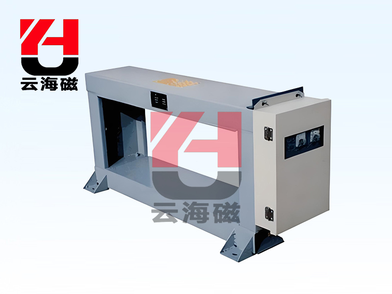
GJT metal detector
Product Introduction
The GJT series metal detector is mainly used in belt conveyors in industries such as mining (stone, iron, gold, etc.), cement, coal preparation, thermal power generation, metallurgy, chemical industry, papermaking, forestry, environmental protection, building materials, etc. It utilizes the change signal generated when metal enters the sensor electromagnetic field, processes it through electronic technology, and drives the actuator (electromagnet, motor switch) to move, thereby discharging harmful metals and detecting and eliminating metal foreign objects to improve product quality and ensure the safe operation of equipment.
working principle
Metal detection technology - digital phase shifting and digital detection technology - has been applied in circuit design, with high sensitivity design. 220V AC power is converted into DC power supply, and high-frequency current is supplied to the sensor through digital circuits to form a high-frequency magnetic field. When metal passes through the sensor, eddy currents are generated in the metal. The amplified output signal is sent back to the control circuit through an amplification circuit to generate a control signal, which controls the drive circuit to output an alarm indication and external output action. This achieves the use of the weak change signal generated when the metal enters the electromagnetic field range of the sensor. The industrial control digital circuit analyzes and processes it and drives the actuator to act, thereby eliminating hazardous metals. The detection sensitivity can reach up to 20mm iron and aluminum balls, and the sensitivity debugging is simple and convenient. The sensitivity may vary with different sensors.
Technical Features
The foot installation size of the sensor is based on the dimensions given by the GB.TD-75 tape conveyor frame, making installation simple.
2. The control box can transmit up to five meters away, avoiding the impact of harsh on-site environments.
3. Multiple anti-interference measures have been adopted to effectively prevent misoperation.
4. Able to detect various magnetic and non-magnetic materials.
5. Users can choose whether to use DCS (Distributed Control System) interface. The start and stop of the instrument can be remotely controlled, and information such as readiness, operation, and malfunction can be transmitted to the central control room.
6. The control box adopts IP54 standard design, dust-proof structure, internal and external spraying, and strong corrosion resistance.
7. Intelligent sensitivity adjustment.
8. Adjustable grade, belt speed, ore type, good stability, and strong usability.
9. Strong universality and simple product upgrade and replacement.
Installation location and precautions
1) The installation size of the sensor foot is based on the dimensions given by the GB.TD-75 tape conveyor frame, with a hole diameter of 16mm and fixed with 14 bolts.
2) The installation environment of the sensor should have no large metal components moving and try to avoid interference from strong electromagnetic fields, especially walkie talkies Welding machines and large electromechanical equipment, etc.
3) The metal detector should be installed in the middle of two rollers, with a distance of not less than 70cm between the rollers. If the distance between the rollers does not meet the requirements The rotating rollers can cause unstable effects on the metal detector.
4) The vibration of the belt conveyor can have a significant impact on the lifespan of the sensor and the stability of the system. It is strongly recommended to install a separate bracket for fixing the metal detector during installation.
5) During installation, there should be no contact between the bottom of the sensor and the bottom of the belt. The optimal distance is 2-3cm between the bottom of the belt and the bottom of the sensor when there is material on the belt.
6) If the detector is used in conjunction with a belt type iron remover or a disc type iron remover, the distance between the sensor and the iron remover should be greater than 2 meters. In special cases where the distance is close, the installation method should be determined based on the site conditions.
7) After installation, it is necessary to check whether the screws in each part are tightened, otherwise it is easy to cause misoperation during vibration.
8) When disassembling and reassembling, the connections of each part must be secure and there must be no poor contact, otherwise it will cause abnormal detection.

Technical Specifications
| Project/Parameters/Model | Adaptive bandwidth mm | Power ≤ kw | Adaptability band m/s | Input voltage~v | Sensitivity ≥ mm | Weight kg | Dimensions mm |
| A | B | C | D | E | L | L1 |
| GJT-5F | 500 | 40 |
0.8-2.5 |
220± 10%50HZ |
φ20 Iron aluminum ball | 105 | 820 | 690 | 250 | 410 | 250 | 740 | 300 |
| GJT-6F | 650 | 40 | 125 | 1000 | 840 | 250 | 410 | 250 | 890 | 300 |
| GJT-8F | 800 | 50 | 160 | 1200 | 1010 | 250 | 410 | 250 | 1090 | 300 |
| GJT-10F | 1000 | 50 | 190 | 1400 | 1240 | 250 | 410 | 250 | 1320 | 300 |
| GJT-12F | 1200 | 50 | 255 | 1630 | 1470 | 250 | 430 | 300 | 1550 | 370 |
| GJT-14F | 1400 | 60 | 290 | 1830 | 1680 | 250 | 430 | 300 | 1740 | 370 |
| GJT-16F | 1600 | 60 | 350 | 2050 | 1890 | 250 | 430 | 300 | 1950 | 370 |
| GJT-18F | 1800 | 65 | 430 | 2280 | 2120 | 250 | 430 | 300 | 2180 | 370 |
| GJT-20F | 2000 | 70 | 480 | 2500 | 2340 | 250 | 430 | 300 | 2400 | 370 |
product image
on-site installation